Blog

How Photogrammetry Builds Plant 3D Models From Photos

From stereo parallax and camera poses to dense clouds, textured meshes, and georeferenced plant models you can load into a digital twin.

  • Patrik Pasko

  • August 27, 2026

twinzo logistics analytics on a phone
How Photogrammetry Builds Plant 3D Models From Photos

CAD Says Clear Aisle, Forklift Hits a New Rack

Second shift starts a tugger trial on the east hall. The layout PDF from engineering still shows a wide aisle between presses and the big-bag buffer. On the floor that aisle closed six months ago when packaging dropped a new rack bank overnight. The driver follows the drawing, not the hall, and stops short against steel that was never on the twin. Logistics blames the map. Engineering blames the undocumented move. Both are right about their own files. Neither has a 3D model of the plant as it stands tonight.

Brownfield sites live this gap constantly. Industry practice already treats as-built surveys as mandatory before major layout changes, fire-route reviews, or AGV path design, because paper CAD drifts the moment maintenance relocates a column guard, a charging station, or a temporary buffer. Photogrammetry closes that gap by recovering metric geometry from photographs of the real hall: machines, floor paint, clutter, and the rack that nobody drew. When that mesh becomes the twinzo facility model, the next route trial runs against the aisle people walk, not the aisle last year's drawing promised.

Typical moment: a weekend line move finishes Sunday night. Monday morning RTLS and forklift analytics still sit on last week's walls. Someone walks the hall with a camera or flies the yard, processes the capture through alignment, dense reconstruction, and meshing, then swaps the model under the same live positions. Operators open 3D and recognize their presses. That is the operational job. The rest of this article is the technical path that makes that mesh possible.

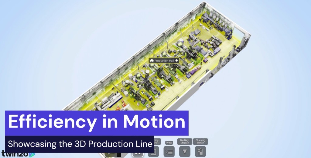
twinzo 3D production hall mesh from photogrammetry with presses, floor paths, and area labels

What Photogrammetry Actually Measures

Photogrammetry is the measurement of shape and position from photographs. It does not invent depth from a single image. It uses the same geometric fact stereo vision uses: a point on a surface projects to different pixel locations when the camera moves, and that parallax encodes distance once you know the relative pose of the cameras and their internal optics.

Classical aerial photogrammetry formalized this with the collinearity equations. A 3D object point, the camera projection center, and the image point lie on one ray. With two or more calibrated views of the same point, those rays intersect in object space. Modern Structure-from-Motion (SfM) and Multi-View Stereo (MVS) automate that idea at plant scale. They recover camera poses and sparse structure from unordered photo sets, then densify the cloud until every well-textured surface has enough samples to mesh.

That is why overlapping coverage is mandatory. One photo of a press bay is documentation. Fifty photos with high forward and side overlap are a measurable volume. Without baseline between views, parallax collapses and depth becomes unstable. Without texture that the matcher can lock onto, rays never find reliable correspondences. Photogrammetry is optics plus geometry plus image matching, not a filter that '3D-ifies' a single frame.

Pipeline: Features, Poses, Dense Cloud, Mesh, Texture

Production tools (RealityCapture, Agisoft Metashape, Autodesk ReCap, Pix4D, and survey vendor suites) hide the math behind stages, but the stages are consistent.

1. Feature detection and description - Algorithms such as SIFT, SURF, AKAZE, or learned detectors find keypoints that stay stable under viewpoint and lighting change: bolt heads, logos, floor paint corners, rack joints. Each keypoint gets a descriptor vector used for matching across images.

2. Feature matching and geometric verification - Putative matches are filtered with epipolar constraints and RANSAC so wrong pairs from repeating racks or identical machines do not corrupt the solution. Remaining matches become the observations that drive pose estimation.

3. Sparse reconstruction and bundle adjustment - Incremental or global SfM estimates extrinsic camera poses (position and orientation) and a sparse 3D point set. Bundle adjustment jointly refines poses, points, and often intrinsic parameters by minimizing reprojection error across the whole block. This is the step that keeps a 200-meter hall from drifting when you walk it end to end.

4. Dense Multi-View Stereo - Once poses are solid, MVS fills depth for nearly every pixel that has multi-view support. Output is a dense colored point cloud, often tens or hundreds of millions of points for a plant hall.

5. Meshing and texturing - Surface reconstruction (Poisson, Delaunay, or proprietary variants) grows a triangle mesh through the cloud. Photo textures are projected or blended onto that mesh so operators see presses and aisle paint, not a grey shell.

If any early stage is weak, later stages cannot rescue it. Bad overlap or motion blur fails matching. Soft bundle adjustment fails scale and aisle width. Thin dense coverage fails meshing around machines. Treat the pipeline as a chain with known weak links, not as a one-click magic button.

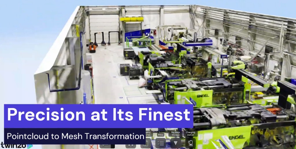
Point cloud to mesh transformation of an injection molding hall with ENGEL presses in twinzo

Capture Geometry: Overlap, Baseline, and GSD

Capture planning is where most plant projects succeed or fail before software opens. Overlap is the fraction of scene content shared between neighboring images. UAV mapping practice commonly targets roughly 70–80% forward overlap and 60–70% side overlap for nadir grids. Terrestrial hall walks need the same idea in 3D: every surface you care about should appear in several frames from meaningfully different angles, not from a single orbit that never changes baseline.

Baseline (distance between camera positions) trades against matching difficulty. Too small and depth noise grows because parallax is tiny. Too large and correspondence fails on complex machines with occlusion. Good capture keeps successive frames close enough to match, while still spanning enough viewpoint diversity around racks and presses that hidden faces get covered on later passes.

Ground Sample Distance (GSD) is the real-world size of one pixel on the surface. Lower GSD (finer) means more detail and heavier processing. Indoor twin work that must show aisle paint and machine silhouettes usually needs finer GSD than a campus roof model that only needs building footprints. Flight height, focal length, and sensor pixel pitch set outdoor GSD. Walking distance and lens choice set indoor GSD. If you need sub-centimeter edges for AGV clearance checks, plan capture accordingly. A pretty but coarse mesh will not answer that measurement.

Cameras, Intrinsics, and Why Calibration Matters

Every photo is interpreted through a camera model: focal length, principal point, and lens distortion (radial and tangential). Photogrammetry can estimate many of those intrinsics during bundle adjustment, especially with many convergent views. It still helps to use a stable lens, fixed focal length, and consistent settings. Zoom lenses and heavy rolling shutter from cheap video frames add systematic error that looks like warped aisles or bowed walls.

Prefer still frames with low ISO noise, fast enough shutter to freeze walking motion, and depth of field that keeps the working volume sharp. Motion blur kills keypoints. High compression kills fine texture. RAW or high-quality JPEG from a DSLR or industrial camera outperforms casual phone video for hall-scale metric work, even though phones are fine for small pilot cells when expectations match the sensor.

Exposure consistency across a long hall matters for texturing more than for geometry. Huge lighting swings between sunny dock doors and dark machine pits produce texture seams and matching dropouts. Teams often scan by zone under controllable light, or accept that texture quality will vary and keep measurement trust on well-lit, well-overlapped structure.

Scale, Control Points, and Plant Grid Alignment

An unscaled SfM reconstruction is defined only up to similarity. It can look correct and still measure wrong. For digital twin use you need absolute scale and, ideally, registration to the plant coordinate system so RTLS tracks, ERP bin coordinates, CAD walls, and the photogrammetry mesh share one floor.

Common methods: measured scale bars or known tape distances between marked points, Ground Control Points (GCPs) surveyed with total station or GNSS outdoors, and alignment to existing CAD control or building grid. Bundle adjustment can constrain those observations so the whole block snaps to meters and orientation. Check residuals. High GCP error means bad survey, bad target visibility, or a deformed block that needs more overlap or a split into zones.

Without this step, area occurrence and path simulation lie with confidence. A dock that looks right on screen but is 4% short will misplace every truck pin and every no-go edge you draw in twinzo. Treat georeferencing as part of the scan job, not as optional polish after the pretty mesh is done.

How Models Are Created: Handheld, Hall, Drone, Satellite

The reconstruction math is the same. The acquisition platform changes coverage, GSD, and failure modes.

• Handheld and phone or tablet - Systematic orbits around a cell or buffer. Good for pilots and machine islands. Weak for multi-hectare sites unless you accept many sessions and careful block merging. Watch rolling shutter and auto exposure.

• Terrestrial camera networks and carts - DSLR or industrial cameras on poles, tripods, or trolleys, sometimes paired with LiDAR. Best for hall-scale indoor detail when you can slow traffic. Convergent photos of facades and machine rows improve depth on vertical surfaces that nadir-only capture misses.

• UAV / drone photogrammetry - Grid flights with nadir imagery for roofs and yards, plus oblique passes for dock faces and building shells. Standard for gate-to-dock campus geometry. Flight planning sets GSD, overlap, and wind limits. RTK or PPK GNSS on the aircraft reduces GCP count outdoors but does not replace check points.

• Manned aerial and satellite stereo - Pushbroom or frame aerial surveys and stereo/multi-view satellite products produce DEMs and textured terrain at regional scale. Resolution is coarser than a hall walk, yet elevation, footprints, and corridor context are enough for campus twins, logistics parks, and outdoor route planning where flying every hectare at indoor GSD is impossible.

Plants usually layer these. Terrestrial or hybrid indoors for presses and aisles, UAV for yards, satellite or aerial DEM for wider terrain. twinzo can host the combined meshes so dock asphalt from the drone sits next to the press row from the hall block without forcing one sensor everywhere.

Aerial photogrammetry terrain mesh of a river landscape with contour lines showing elevation structure

Where Matching Breaks: Texture, Specular, Occlusion

Dense reconstruction needs unique, stable appearance. Featureless white walls, polished stainless, glossy epoxy floors, glass, and repeating identical racks are classic industrial failure modes. Specular highlights move with the camera, so the matcher treats them as different surfaces. Transparent and reflective materials violate the opaque Lambertian assumptions built into many MVS methods.

Mitigations used on real sites: temporary coded targets or tape markers on blank walls, added temporary texture (removable matte film) on critical panels, polarized or controlled lighting, scanning shiny cells with LiDAR for structure while keeping photogrammetry texture elsewhere, and accepting holes that you fill with CAD primitives. Moving people, forklifts, and hanging soft goods also create ghost geometry. Capture during planned windows when traffic is quiet, or mask moving objects in processing software when available.

Occlusion is geometric, not photometric. A second row of presses hides the first from many angles. Plan loops that look between machines, not only down the center aisle. If a face never appears in two well-posed images, it will not exist in the dense cloud no matter how high you set quality sliders.

Point Cloud Is Survey Data, Mesh Is Twin Data

The dense cloud is the right deliverable for measurement, clash detection, and archival survey. It is the wrong everyday object for a shift lead on a tablet. Points do not shade like walls, pick poorly for area drawing, and choke browsers when you treat a multi-gigabyte LAS or E57 as an interactive hall.

Meshing converts samples into a surface. Poisson reconstruction and related methods estimate an implicit surface from oriented points, then extract a triangle mesh. Cleanup removes floating noise, thin sheets from people who walked through the scan, and spikes on specular metal. Decimation reduces triangle count in empty volumes while preserving edges on aisles and machine silhouettes people use as landmarks. Texturing bakes photo color onto UV charts or uses per-triangle projection blends.

Typical handoff: Friday survey ships a dense cloud. Modeling produces a textured FBX or OBJ under size limits interactive platforms expect. Monday the same production hall sits in twinzo with labels for Press, Big Bags Storage, and Charging station. Contour overlays may still appear during processing as elevation checks, but operators navigate the mesh. The cloud did the metrology job. The mesh does the twin job.

Satellite Stereo and Terrain Models at Campus Scale

Satellite photogrammetry uses stereo or multi-view image pairs collected from different orbital geometries. Along-track or across-track stereo provides the parallax needed for Digital Surface Models (DSM) and Digital Elevation Models (DEM). Rational Polynomial Coefficients (RPCs) or rigorous sensor models replace the simple pinhole pose of a handheld camera, but the measurement idea is unchanged: corresponding image points intersect in object space once orientation is known.

Resolution depends on the constellation and product. Sub-meter commercial imagery can outline buildings, yards, and roads well enough for campus twins and regional logistics. It will not replace a terrestrial hall scan for press spacing. Contour lines on a terrain mesh are a direct visualization of that elevation field, useful when grade, drainage, flood paths, or outdoor access roads affect gate-to-dock routing and emergency planning.

Use satellite and manned aerial photogrammetry for context and terrain. Use UAV and hall capture for dock faces, aisle widths, and machine recognition. Layering coarse exterior with fine interior is standard survey practice, not a compromise. It keeps outdoor path simulation honest without demanding indoor GSD over every surrounding hectare.

Photogrammetry Versus LiDAR on the Same Site

LiDAR measures range with time-of-flight or phase difference of laser returns. Photogrammetry measures range indirectly from image parallax. Both can output point clouds and meshes. Accuracy behavior differs by surface. Dark, specular, or transparent materials break photo matching. Some LiDAR returns struggle with specular misses or multipath, yet LiDAR often wins on textureless walls where photogrammetry finds no keypoints. Photogrammetry usually wins on color texture and visual recognition without a separate camera pass, and outdoor UAV photogrammetry is often cheaper per hectare for yards.

Hybrids are common in industry mapping trolleys and survey workflows: LiDAR for structural cloud, cameras for texture and for filling photo-friendly zones. The twin does not care which sensor produced each triangle if the final mesh is scaled, clean, and recognizable. What fails ops is a beautiful unscaled cloud that never becomes a navigable model, or a CAD-only twin that ignores last month's rack move. Choose for the failure mode. Outdated drawings and missing outdoor context lean photogrammetry. Metrology on polished equipment lean LiDAR or hybrid.

From Mesh Into twinzo Jobs on Real Geometry

Photogrammetry stops being a survey project when the mesh sits under live work. In twinzo you import the hall or yard model, align it to floor plan and plant coordinates, then run the jobs that needed true geometry in the first place: place an untagged supplier truck, simulate gate-to-dock movement, draw areas, read occurrence and dwell, notify on no-go entry.

1. Capture - plan overlap, GSD, and platform per zone (handheld, hall, drone, satellite).

2. Reconstruct - features, matching, bundle adjustment, dense MVS.

3. Control - scale bars, GCPs, plant grid registration, residual checks.

4. Optimize - clean, mesh, texture, decimate, export FBX or OBJ for interactive use.

5. Combine - add CAD or Blender assets where scan is weak or a new line exists only as engineering data. Vendor capture stacks such as NavVis or Leica fit the same pipeline described in how to scan your facility.

6. Operate - RTLS, IoT, and placed assets on that combined model with analytics and alerts.

You do not need a perfect whole-site capture before the first useful twin. Scan the east hall that broke the tugger trial. Fly the yard that owns inbound dwell. Leave a future wing as CAD until it is built. Mixed 3D is how brownfield sites stay metric without endless resurvey of quiet corners.

Rescan Triggers and Adjacent Technical Jobs

A photogrammetry model ages like a drawing. The next weekend rebuild makes it wrong again. Facilities or industrial engineering should own the as-built mesh. Production owns freeze windows for capture. Logistics owns yard resurveys when curb lines change. Trigger a partial block when a line moves, a rack bank appears, or outdoor staging is restriped. Reprocess that zone, swap the patch, re-check control against the plant grid. Freshness is a measurement requirement. Analytics on six-month-old geometry teach the wrong map.

The same current mesh unlocks adjacent work:

• AGV and AMR clearance reviews - measure against the aisle that exists, not CAD clearance that vanished.

• Fire and egress checks - routes against real clutter captured in the cloud-to-mesh.

• Capex layout debates - drop proposed CAD into photogrammetry brownfield and see neighbor clashes.

• Contractor induction - show the hall before the first badge print.

• Incident replay - place people and vehicles on geometry that matches the real bay.

Start With the Block That Already Lies on Paper

Pick the zone where drawings already failed: closed aisle, real yard pocket, press row operators recognize. Plan overlap and GSD for that job, run the pipeline through controlled scale, turn the dense cloud into a navigable mesh, load it into the twin, and run the next path or no-go decision on geometry that matches the shift.

Get in touch if you want to walk through this on your own facility model.

You might also be interested in:

Correlate Plant Systems by Space on the Digital Twin

Correlate Plant Systems by Space on the Digital Twin

Gate open next to an HVAC zone, voltage imbalance on the same energy lane as rising scrap, smart bins ignored by the forklift loop. Put the signals on one map and the nearby impacts stop living in separate dashboards.

Read more
Ignition MES Integration With the twinzo Digital Twin

Ignition MES Integration With the twinzo Digital Twin

Ignition is the SCADA and MES platform many plants already run. Here is who uses it, how Gateway tags and modules work, and how the twinzo plugin maps that data onto a live 3D twin.

Read more

Landscape mode is not supported, please rotate your device.

By clicking “Accept”, you agree to the storing of cookies on your device to enhance site navigation, analyze site usage, and assist in our marketing efforts. View our Privacy Policy for more information.